Design
Before we started even thinking about designing our RC aircraft, critical research was done. The research what took place was to find stuff what was already on the market and see how our design could be different to others out there. Next we started to ask the of what the RC aircraft purpose would be. All our thoughts came together and we all decided on a trainer RC aircraft. We picked to design a RC aircraft because we thought we should keep it simple, as complexity is great we did not want to confuse ourselves in the design. After researching trainer aircrafts, we started to get an idea of what consists within a trainer aircraft; we all then started to draw a initial design on paper.


After the initial drawing where complete on paper, a decision matrix was used for the justification of the design to go forward with. The decision matrix contained the constraints (criteria) what was given to us on the assignment brief. We thought these was key things to include in the decision matrix in order to get the best possible design to fit our target goals.
Ease of Access- This was included for the electronics being easily placed in the aircraft.
Budget- We did not want to go above the budget as this would not meet the criteria.
Appearance- We wanted it to look good as well as have the best performance possible.
Size- The size of the wing span was 1.5 metres and we did not want to exceed over this amount.
Parts- We wanted to keep it simple with the lowest number of point but still giving the RC aircraft the strength and durability it needed with ribs and spars.

The decision matrix gave us a justification of each design concept we came up with. As we was going through the decision matrix, as a team, we all noticed that each design concept had all sort of advantages. We then thought to merge different parts and configurations together from each concept.
After the decision matrix of which design concept is the best fit regarding the requirements, the aircraft sizing calculations which are calculated to initiate the 3D solid works design which will then be enhanced and upgraded along the way. The initial aircraft calculations are shown below:


Initial Design Improvements on CAD

Final Design


Power Calculations and Component Selection
This is your Text paragraph. It’s a great place to add a description of your business, your site or what you do. Use this space to add information for your users, write about your philosophy or your journey and define your distinguishing qualities. Consider adding an image for extra engagement.
After the decision matrix of which design concept is the best fit regarding the requirements, an attempt of the aircraft sizing calculations which are calculated to initiate the 3D solid works design which will then be enhanced and upgraded along the way. The initial aircraft calculations are shown below:
Wingspan = 1 meter
Chord = 0.23 meters
Fuselage = 75% of wingspan
75% × 1 𝑚𝑒𝑡𝑒𝑟=0.75𝑚75% × 1 meter=0.75m
(F)
Distance between thrust and wing
=
1.5×0.23=0.345𝑚1.5×0.23=0.345m
(F1)
Distance between wing and chord
=
2.5×0.23=0.575𝑚 2.5×0.23=0.575m
(F2)
Fuselage height
=
10% 𝑜𝑓 𝑓𝑢𝑠𝑒𝑙𝑎𝑔𝑒 𝑙𝑒𝑛𝑔𝑡ℎ10% of fuselage length
=10%×0.75𝑚=0.075𝑚=10%×0.75m=0.075m
(F3)
Aileron = ¼ of chord
=
14×0.23=0.0575𝑚14×0.23=0.0575m
Strip aileron
=
18×0.23=0.02875𝑚 18×0.23=0.02875m
Wing area
1000𝑚𝑚×23𝑚𝑚=23000𝑚𝑚 (2.3𝑚)1000mm×23mm=23000mm (2.3m)
Stab area
15% of wing area
15%×2.3𝑚=0.345𝑚215%×2.3m=0.345m2
Elevator area
20% of stab area
20%×0.345=0.069𝑚220%×0.345=0.069m2
Fin area
33% of stab area
33%×0.345=0.11385𝑚233%×0.345=0.11385m2
Third or half of the fin.
12×0.11385=0.057𝑚212×0.11385=0.057mm
Balance point
25% to 33% of the chord
30%×0.23=0.06930%×0.23=0.069
AC of wing
14𝑜𝑓 𝑐ℎ𝑜𝑟𝑑 14of chord
14×0.23=0.0575𝑚14×0.23=0.0575m
The matlab code used for these calculations can be found attached here.
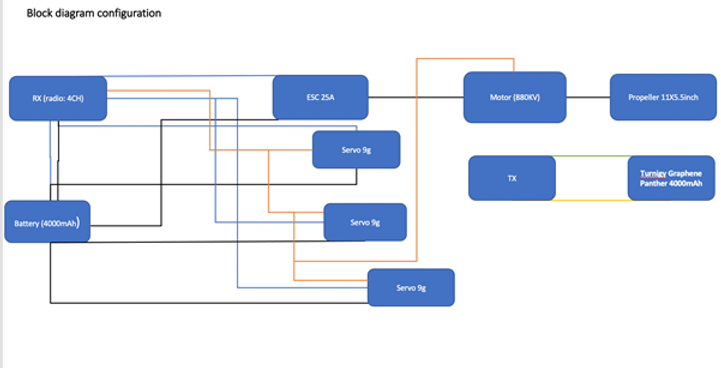
Systems block diagram